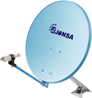
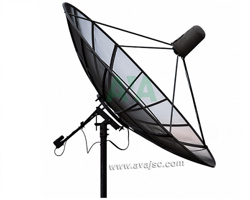
Anten Parabol chảo Comstar 2.3m ST 7.5
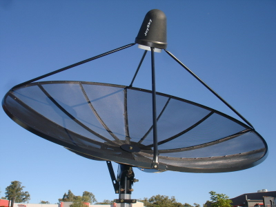
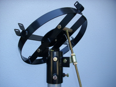
Anten Parabol chảo Comstar 2.3m ST 7.5 Dùng trong hệ thống truyền hình cáp. Là anten Band C dân dụng, dùng thu bắt tín hiệu vệ tinh băng tần C ( có thể dùng để thu băng tần Ku ), chất liệu lưới thép mạ, 4 tấm ghép lại, sơn tĩnh điện có khả năng chống ăn mòn cao. Được thiết kế để hoạt động ổn định bền bỉ, thu tín hiệu chính xác. Thu được hầu hết các vệ tinh có phủ sóng Band C tại khu vực VN… Khung lắp có thể điều chỉnh cho phù hợp với các kích thước khác nhau của cột lắp, khối lượng ~19kg lắp đặt thi công đơn giản.
Là sản phẩm của COMSTAR Group, là một trong những nhà sản xuất hàng đầu trong lĩnh vực anten vệ tinh. Với hơn 20 năm kinh nghiệm trong việc phát triển và sản xuất anten lưới cho thị trường quốc tế.
Sản phẩm bao gồm anten parabol lưới hoặc tấm 1.8 m, 2.3 m, 3.0 m, 3.7 m, 4.5 m, 4,9 m, 6,1 m, 7,2 m, 9,0 m…Sản phẩm tập trung vào kiểm soát chất lượng nghiêm ngặt, hoạt động bền bỉ và liên tục.
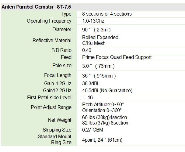
Bảng thông số kỹ thuật chi tiết Anten Parabol lưới Comstar 2.3m – ST 75
HƯỚNG DẪN LẮP ĐẶT ANTEN PARABOL COMSTAR
C/Ku MESH
The Ku mesh design ensures optimum performance for both C/Ku and S bands.
INTERMEDIATE SUPPORT RING
An intermediate support ring welded between the antenna ribs forms the mesh into a compound curve-increasing reflective efficiency.
8 POINT POLAR MOUNT
The 8 point 32″ring attachment provides a more rigid mount than a conventional 4 point attachment. A 4 point 24″ring is also available.
3/4″SHOULDER BUSHINGS
The 2 shoulder bushings provide a maintenance-free smooth polar pivot on the pre-assembled mount.
POWER-COAT FINISH
The finish coat consists of a thermo set resin that provides excellent weather protection.
ALL ALUMINUM REFLECTOR
The new DESIGN is lighter, stronger, and more durable because of its all-aluminum construction.
UNIQUE EXTRUDED BRIDGE RIB
This additional center bridge rib, extruded between the sidewalls, provides more strength than a conventional hollow rib. Standard on all ST Models.
QUAD FEED SUPPORT
A quad feed support, standard on the ANTENNT assures fast and accurate centering of the feed assembly.
INTRODUCTION
Congratulations! You have made a wise investment by purchasing this SECTIONAL ANTENNA. This product will provide you with information. entertainment, and many years of trouble-free service.
The heavy duty mount is a collective effort of industry-educated designers and engineers concerned with strength, durability and performance.
The reflector, constructed of aircraft quality aluminum with powder coated finish, meets the enduring standards of every season.
PRE-ASSEMBLY INFORMATION
PARTS LIST
QUAD BOX:
ST-7 4 Reflector panels
ST-10 8 Reflector panels
ST-12 8 Reflector panels
MOUNT BOX:
1-Pre-assembled Mount
1-7# Actuator
2-Center Hub Plates
1-Bolt Bag (Optional Feed Horn Enclosure)
FEED SUPPORT BOX: 4 Feed Support Rods
AUXILIARY SUPPORT BOX: 8 – Optional High wind support truss (ST-12 only)
TOOLS NEEDED FOR ASSEMBLY
1-1/2〞, 7/16, 10/12〞and 14〞Open End Wrenches
1-16〞Adjustable Wrench
1-Steel Tape Measure
1-7/16〞Socket and Ratchet
1- 3/4〞Open End Wrench
POLE FOUNDATION REQUIREMENTS
Diameter requirement for the ground pole is 3-1/2〞outside diameter. (For all ST models). The pole should extend a minimum of four feet underground for the 10ˊБ12ˊantenna. The foundation should be supported with a minimum of 2500 pounds of cement in normal soil conditions. Less foundation material is required for the 7ˊantenna and a larger foundation for the 12ˊantenna. It is necessary for the pole to be plumb; this allows the antenna to track the entire arc of satellites perfectly. Consult a building contractor in your area for more information on local soil conditions.
ABOVE GROUND POLENGTH
The ground pole should be at least five feet above ground for the Southern United States; six feed above ground for the Northern United States. Pole length for 12’antenna is one foot greater.
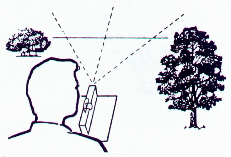
SITE SELECTION
The location of the antenna must have an unobstructed view of all the satellite desired. Also, insure that no large trees, building, etc., prevent a clear field of view.
ECTIONAL ANTENNA ASSEMBLY INSTRUCTIONS
PLWASE READ THE INSTRUCTION MANUAL BEFORE ASSEMBLING!
THIS MANUAL IS MEANT AS A GUIDELINE. MANY INSTALLERS MAY FIND DIFFERENT STEPS OR PROCEDUPES EASIER. THE OBJECT IS TO OBTAIN OPTIMUM PERFORMANCE FROM THE ANTENNA.
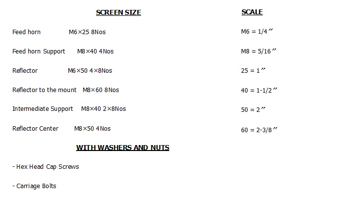
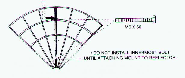
STEP 1 It is necessary to assemble the reflector on a flat surface to ensure proper alignment of the sections. It is a good idea to protect the surface finish by placing cardboard, etc., under the edge of the reflector. Begin by assembling any two quadrants with the M6×50 bolts through the three outermost pre-drilled and the innermost hole of the sections on the ST-10 antenna. Use 14flat washers on both sides of the rib, at each assembly point. When assembling the ST-12 and the ST-7 antennas, do not insert a bolt in the innermost hole at this time. style=”LETTER-SPACING: -0.9pt”>A M8×60 bolt will be inserted in the vacant hole When attaching the reflector to the mount. TIGHTEN FINGER TIGHT ONLY AT THIS TIME.
Please refer to the following for additional assembly instructions for the ST-12 antenna.
STEP 2 Duplicate Step 1 by assembling the remaining two pieces of reflector.
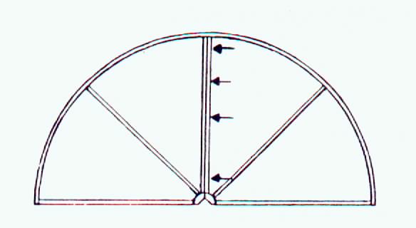
STEP 3 Place another two pieces together, face down, line up the pre-drilled holes and place the M6×50 bolts through the three outermost and one innermost holes. See Figure 3.
TIGHTEN FINGER TIGHT ONLY AT THIS POINT. Now make sure all the reflectors are properly joined and flush at each assembly point. THIS IS VERY IMPORTANT TO ASSURE THE CURVE OF THE REFLECTOR IS MAINTAINED AND SUPPORTED CORRECTLY. Wrench tighten all bolts
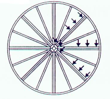
STEP 4 You may stand the assembled reflector on edge for easy access to the center. Attach the center hub plates to the antenna by inserting four M8×50 carriage bolts through the front plate, between the ribs, and through the rear plate on the backside of the reflector. Be sure to use M8 washers on the rear hub plate. See Figure 4. SECURELY TIGHTEN THE CARRIAGE BOLTS WITH A WRENCH.
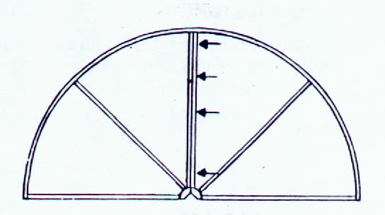
STEP 5 This step involves attaching the quad feed supports. Carefully lay the antenna down on its back so the reflective surface is facing up.
Holes are drilled in each reflector section to accommodate the Quad Feed Support. When attaching the quad feed supports to an eight section antenna, attach the feed supports to every other reflector section. Attach the feed supports so the feed horn servomotor will be positioned correctly to the polar axis as outlined in the feed horn instruction manual.
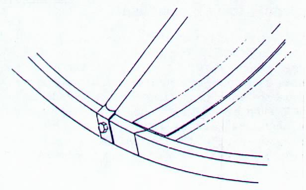
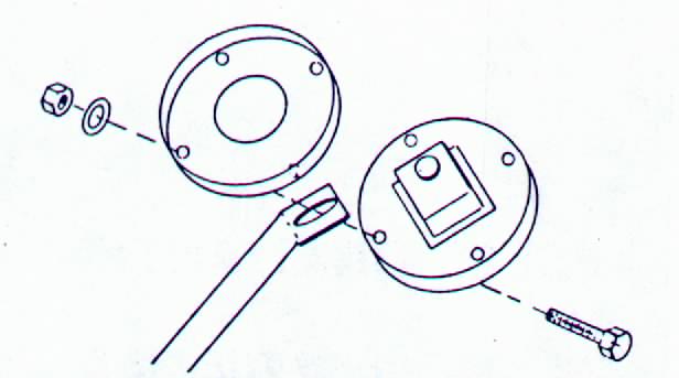
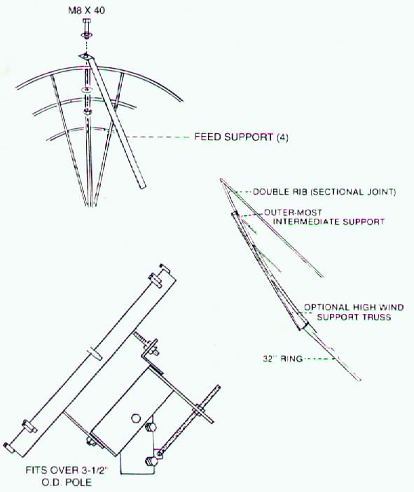
Attach the end of the feed support rod with the round hole to the outside perimeter of the antenna (See Figure 5) with M8×40 bolts. The slotted end of the feed support rod attached to the feed horn (illustrated in Figure 6) with M6×25 bolts. The feed supports should be positioned equally to properly center the feed horn. You may now set the focal length at-36〞 for ST 7, 45-7/8〞for ST10, 57-1/2〞for the ST 12 measuring from the flat center hub plate to the feed horn wave guide. The wave guide is the centermost ring on the feed horn. Adjust the feed horn in or out by 1/8〞to reach its optimum C/Ku band performance. A peak meter is also recommended.
STEP 6 Place the pre-assembled mount over the 3-1/2” outside diameter ground pole.
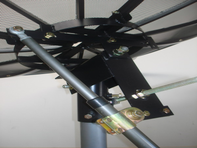
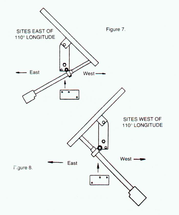
STEP 7 Installation of the #7 actuator bar is recommended on ST-12 Antennas (only) for areas within 10° East or West of the 110° longitude line to give the actuator a better mechanical advantage. Installation of the #7 actuator bar outside this area is not required for proper system operation. The proper actuator bar positioning must be obtained so that the antenna will track the entire arc of satellites. To find that position, you must first locate your latitude and longitude on a map. Refer to Chart 1. Add the actuator bar as per Figure 7 or 8, which shows the proper alignment for your location. Secure the actuator bar with (2) 1/2” x 1-1/2” bolts and locknuts, Now you may install your actuator or hand crank, TIGHTEN ALL BOLTS WITH A WRENVH. The #7 actuator bar is supplied for all models. Attach the actuator directly to the correct side of the elevation U-bracket as shown.
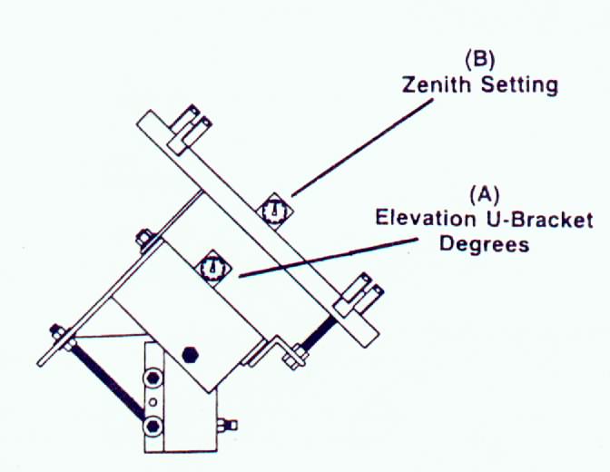
STEP 8 Setting the Elevation/Declination. Rotate the mount ring on the mount pivot axis until the mount ring is parallel with the elevation U-Bracket (as shown in Figure 9) which will be the highest look angle. Refer to the Elevation/Declination Chart; find the latitude of the installation site. Note the Elevation (A) and corresponding declination offset (B) angle for the installation site. Set the Elevation (A) first, then adjust the declination (B) to the correct setting for your site latitude. Securely wrench tighten the declination and elevation setting at this time.
STEP 9 Now attach the completed reflector to the mount. First attach the four wide rib brackets to the reflector with M8×60 bolts. Repeat this procedure also with the four rib brackets (Applied 12’only) WRENCH TIGHTEN ALL BOLTS.
STEP 10 The antenna assembly is now complete. Make sure that all the bolts and nuts are securely wrench tightened. Please check the focal length measurement; and be sure the feed horn is centered and properly secured. IMPORTANT: TO optimize the antenna’s performance, it is recommended that a bore sight tool be used to ensure that the feed horn is aimed directly at the center of the antenna. This antenna is now ready to adjust for tracking.
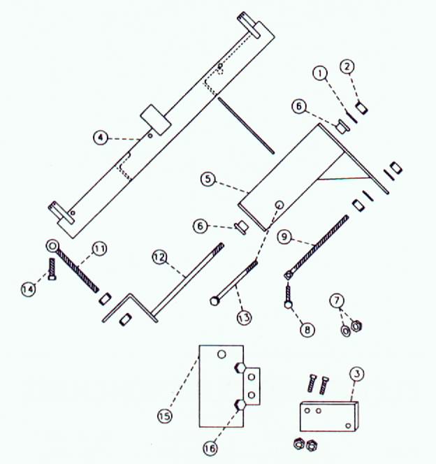
PART DESCRIPTION
1 Lock Washer
2 Polar Pivot Nut
3 7# Actuator Bar, Bolts and Nuts
4 Mount Ring with 8 Attached Rib Brackets on 32〞Ring. (24〞Ring has 4 Rib Brackets)
5 Elevation U Bracket
6 3/4〞Shoulder bushing (2)
7 Elevation Pivot Lock Washer and Nut
8 Elevation Adjustment Bolt with Nut
9 Elevation Adjustment Rod with 2 Nuts and 2 Flat Washer
11 Elination Adjustment Eye Bolt with 2 Nuts
12 Polar Pivot Bolt
13 Elevation Pivot Bolt
14 Eye Bolt Bolt
15 Pipe Socket Bracket
16 Pipe Socket Securing Bolts (4)
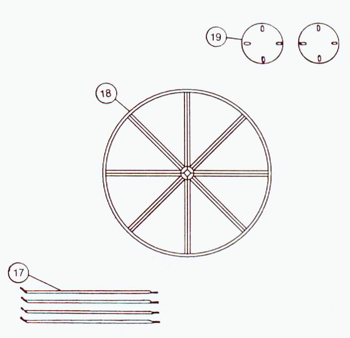
17 Feed Support Rods (4)
18 Reflector Panels (8), ST-12 (8), ST-10 (6 or 8)
19 Center Hub Plates (2)
12 Foot – 8 Section Reflector
Focal Length: 57 – 1/2〞
NOTE: When the optional high wind support trussing is used: Do not install the second bolt form the outside until the mount is on the reflector face.
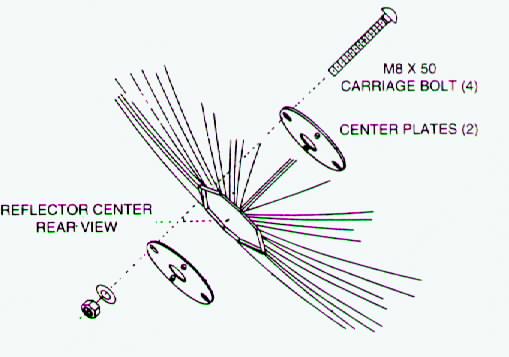
The center plate is designed to center over the center hole in the reflector with the carriage bolts passing through the center hole of the reflector.
When assembly is complete on both halves, lay face down and join haves together to complete reflector assembly.
NOTE: ALL FASTENERS SHOULD BE FINGER TIGHT ONLY. WRENCH TIGHTEN ALL FASHENERS ONLY AFTER THE HALVES ARE JOINED TOGETHER.
After antenna face bolts are tightened, place mount on reflector. Then install M8×60 full thread bolt through mount saddle brackets. Now install optional high wind support trusses.
NOTE: When placing the mount on the reflector. DO NOT wrench tighten until all fasteners are in place finger tight.
The center plate install
HOW TO LOCATE SATELLITES…
Make sure the declination is properly set as shown in Figure 9; this is the most important part of getting your antenna to track properly.
The heavy-duty mount allows for in finite declination adjustment form 0 to 10 degrees off the elevation setting.
You will need to know your location’s latitude. These can usually be found on the edge of Road Atlas maps.
1. Once you have determined the longitude of your site, select the satellite with a longitude closest to yours. This will be the most southerly satellite at your location.
2. Calculate the degree difference between the site longitude and the satellite longitude.
3. Set the declination offset angle and elevation adjustment as shown in Figure 9.
4. Determine true south at your location, and adjust the pipe socket bracket so that the bottom of the elevation U bracket is pointed
at true south. Tighten the bolts on the pipe socket bracket.
5. Adjust the reflector face with the actuator so that it also faces true south.
6. Now you should be able to locate the most southerly satellite by loosening the bolts on the pipe socket bracket and rotating the antenna on the pope until the satellite is located. IT IS IMPORTANT THAT YOU DETERMINE WHICH TRANSPONDERS ARE ACTIVE ON THE SATELLITE YOU ARE LOOKING FOR, SO YOUR ELECTRONICS CAN BE PROPERLY TUNED.
7. Once the satellite is located, the signal should be peaked by making slight adjustments to the elevation and east or west azimuth. DO NOT MAKE CHANGES TO THE DECLINATION ADJUSTMENT.
SETTING THE REFLECTOR TO TRACK…
Now that you have located the most southerly satellite, use the actuator or hand crank to move the reflector to the west to find other satellites. Move the reflector westerly, scanning the receiver channels until another satellite is found. Continue westerly until you locate a satellite with a noticeably weak signal. Now, peak the signal using elevation adjustments.
The following steps will determine the final adjustment to true south.
1. If the most westerly satellite transponder clears up by increasing the elevation, the pipe socket bracket must be rotated to move the reflector slightly to the west.
2. If the most westerly satellite transponder clears up by decreasing the elevation, the pipe socket must be rotated slightly to the east.
3. After adjustments are made to the north-south orientate of the reflector, return to the first satellite located; repeat the signal and repeat the above procedure until the reflector tracks all the westerly satellites accessible at your location.
At this point, slight adjustments to the declination can be used to optimize tracking over the entire satellite belt.
TROUBLE SHOOTING…
1. No picture. Is receiver on? Is TV on correct channel? Did you check all cable connections?
2. Picture, but no sound. TV not fine tuned. Check for loose connections.
3. Receiver only tunes some channels. All satellites do not have 24 active transponders. Check to see that the satellite you are viewing has an active transponder. Make sure that the “tune ”voltage wire has not been switched with the LNB B + wire. This is a common problem.
4. Faint image. Antenna not aligned properly? Feed horn not centered? Incorrect focal point? Problems with LNB, Cable, Receiver? Refer to Manufacturers Manual or Service Center of component’s parts.
Because every installation is different, we cannot cover everything in print. If these instructions do not help you isolate or correct any problems you are having, feel free to contact this telephone number to talk with a friendly service representative.
FINAL CHECKLIST
- Is the focal length set properly:
36〞for ST-7
45-7/8〞for ST-10
57-1/2〞for ST-12
- Is the feed horn centered over the reflector and bore sighted at the center of the reflector?
- Is the declination-offset measurement correct?
- Are all bolts securely wrench tightened?
- Are the electronics correctly connected?